The best probe station, made in China!

PRODUCTS

F1 - SiPh Probe Station
· The probe station can be configured by selecting F1+futureC+instrument.
· Please call Eoulu service hotline 4008808776 for professional engineer support!
Category:
Probe Station
Contact Information
CONTACT NOW- Product Features
- Product Mix
- Product Parameters
- Instructions
-
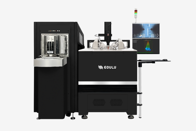
Possess powerful silicon photonics automation
Support O-O, O-E, E-O and E-E test applications

Provide advanced test technology from single fiber to fiber array
Solve the challenges from vertical coupling to edge coupling
-
-
F1 Mechanical Performance
No. Item Chuck X-axis Y-axis Z-axis Theta axis 1 Travel 301 mm 301 mm ≥10 mm 10° 2 Maximum positioning accuracy * ≤ 0.05 μm ≤ 0.05 μm ≤ 1 μm ± 0.003° 3 Speed ** ≥ 50 mm/s ≥ 50 mm/s ≥ 20 mm/s / 4 Maximum speed 150 mm/s 150 mm/s 35 mm/s / 5 Wafer uneveness adaptability * 100 μm 6 Average time of mapping *** Minimum value Typical value Maximum value < 500 ms < 1 s < 3 s**** 7 XY position locking ***** Minimum value Typical value Maximum value 0.02 μm 0.038 μm 1.5 μm 8 Z position locking Minimum value Typical value Maximum value 0.65 μm 3.5 μm 15 μm * When C0 and VR are enabled
** The speed at which F1 chuck moves varies depending on the chuck size chosen by the customer, the chuck construction (Coax or Triax), and whether the chuck supports high and low temperatures
*** This time only refers to the mechanical movement time and does not include alignment time. There will be some variation depending on the size of the DUT, movement precision, and stability requirements
*** High speed and high stability cannot be achieved simultaneously. Eoulu can provide services to optimize test accuracy or test speed according to the customer'swafer and measurement application. For more information, please contact sales for hardware and software upgrade solutions
**** In the case of 8-inch, room temperature, and triax chuck, F1 adopts the highest accuracy and most stable speed mode, 1000 μm * 1000 μm chip movement time
***** It varies according to the configuration and the customer's requirements for accuracy and speed. The minimum value of XY position locking can be achieved by selecting CCD, which cannot be achieved by standard CCD.
****** The standard deviation of the probe scrub mark length σ is ≤ 5μm. We can refer to the futureD product data of Eoulu to measure more than 2,000 DUTs of 8-inch wafers. Under the high-precision wafer running mode, the probe scrub mark length difference from DUT to DUT is guaranteed to be within 3σ
****** The standard deviation of the starting position of the probe mark σ is ≤ 8μm. We can refer to the futureD product data of Eoulu to measure 2000 DUTs of 8-inch wafer. Under the high-precision and low-speed wafer running mode, the difference in starting position from DUT to DUT is guaranteed to be within 3σ
****** The above data indicators are not lower than the level of peers,refer to the article published by the peer on August 22, 2022
F1 Shielding Capability
No. Shielding and Noise Capability * 1 Light attenuation ≥ 150 dB ** 2 EMI shielding ≥ 20 dB 0.5-20 GHz (typical) 3 Spectral noise floor ≤ -150 dBVrms/rtHz (≤ 1 MHz) 4 System AC noise ≤ 15 mVp-p (≤ 1 GHz) 5 * Eoulu F1 low noise test system supports 1/f,RTS,RTN test. When purchasing low noise test probe station, plesase purchase grounding service and
commissioning service
* In addition to the system capability, environmental conditions should also be considered. This project is not verified on the customer side, and can
be arranged to be verified in Suzhou laboratory of Eoulu
* The fully-automated probe station does not have Microchamber,this parameter is not applicable
** The single-photon test requires additional shielding devices,this parameter is not applicable
** The test light path refers to the perpendicular incident light from 90° directly above the microscope
** The light shielding wavelength is 200 ~ 2000 nm
F1 Vibration Isolation Capability
No. Vibration Isolation Capability *
1 Natural frequency (vertical) 2.5 ~ 2.7 Hz 2 Natural frequency (horizontale) 2.0 ~ 4.5 Hz 3 Vertical damping (adjustable) 6% ~ 20% 4 Horizontal damping 5% ~ 6% 5 Air pressure 0.3 ~ 0.5 Mpa 6 Maximum load 1600 kg 7 Isolation efficiency 5% ~ 6% 8 Response time to external excitation < 1 s 9 Vibration isolation level VC-C * For the F1 vibration isolation table related parameters, please refer to the manufacturer traceability index. This project is not verified on the customer side
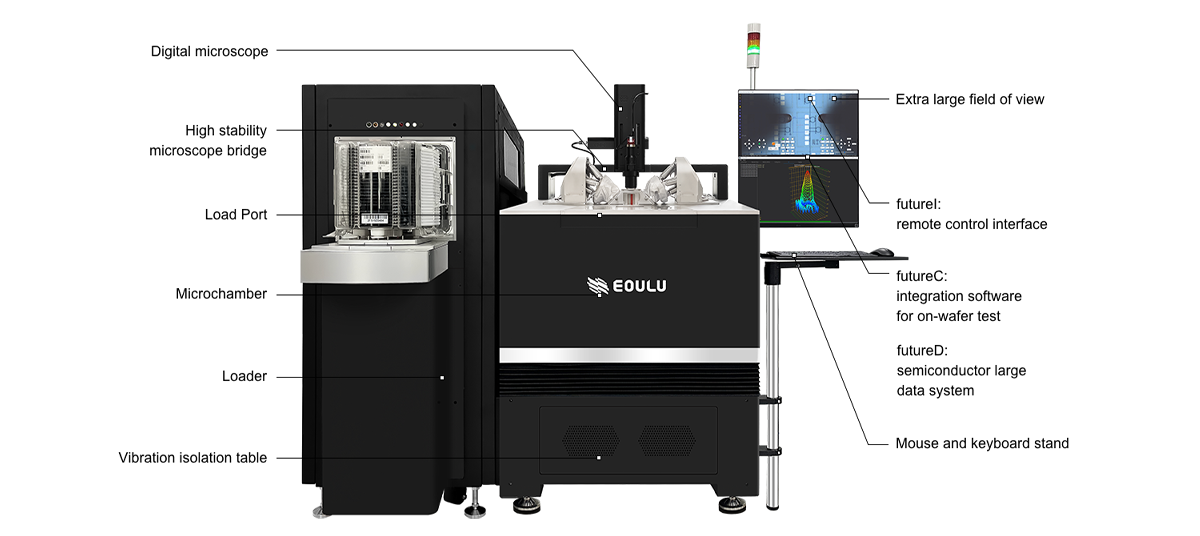
F1 Microscope
Microscope Bridge No Item X-axis Y-axis Z-axis 1 Travel 50 mm 50 mm 90 mm 2 Maximum positioning accuracy ± 2 μm ± 2 μm ± 2 μm 3 Speed 60 mm/s 60 mm/s 120 mm/s Microscope * No Item Large FOV High Resolution 4 Typical magnification ** 225 X 500 ~ 2000X or higher 5 Typical optical lens resolution *** 3.0 μm ≤ 1.5 μm 6 Product picture 

7 futureI image 

* The F1 probe station is available in both Large FOV and High Resolution microscope configurations, you can choose according to your test requirements
** When the CCD configuration is different, the color and magnification will be different
** When the objective lens is different (5X, 10X, 20X, 50X, 100X), the magnification will be different
*** When the lens configuration is different, the resolution will be different
F1 Chuck
No. Item Chuck size 8-inch 12-inch 1 Temperature range Room temperature High and low temperature Room temperature High and low temperature 2 Maximum operating
temperature range *
- -60 ~ 300°C - -60 ~ 300°C 3 Typical temperature range ** - -60 ~ 150°C
-60 ~ 200°C
-60 ~ 300°C
-40 ~ 150°C
-40 ~ 200°C
-40 ~ 300°C
0 ~ 100°C
0 ~ 200°C
Room temperature
~ 150°C
Room temperature
~ 200°C
Room temperature
~ 300°C
- -60 ~ 150°C
-60 ~ 200°C
-60 ~ 300°C
-40 ~ 150°C
-40 ~ 200°C
-40 ~ 300°C
0 ~ 100°C
0 ~ 200°C
Room temperature
~ 150°C
Room temperature
~ 200°C
Room temperature
~ 300°C
4 Temperature accuracy ± 1°C ± 1°C 5 Temperature resolution 0.1°C 0.1°C 6 Triax chuck leakage (non-thermal) ≤ 132 fA ≤ 231 fA 7 Triax chuck noise (non-thermal) ≤ 30 fA ≤ 42 fA 8 Cooling mode Liquid cool and air cool are optional 9 Typical transition time***
(Liquid cool)
- 60°C → 25°C:23 min
25°C → 300°C:28 min
300°C → 25°C:25 min
25°C → - 60°C:37 min
- 60°C → 25°C:23 min
25°C → 300°C:28 min
300°C → 25°C:25 min
25°C → - 60°C:37 min
10 Typical transition time***
(Air cool)
- 60°C → 25°C:9 min
25°C → 300°C:25 min
300°C → 25°C:12 min
25°C → -60°C:29 min
- 60°C → 25°C:9 min
25°C → 300°C:25 min
300°C → 25°C:12 min
25°C → -60°C:29 min
11 Maximum heating power 5.5 kW 12 Maximum cooling power 12.5 kW 13 Maximum refrigerant flow 5 m / s 14 Maximum transport pressure 4 bar 15 Maximum voltage (high power option) *** 10000 V 16 Maximum current (high power option) *** 800 A 17 Statement It shall be operated and stored strictly in accordance with the temperatureand humidity
specified in "Environmental conditions" in this Manual.
Before the probe station leaves the factory, wafers shall be placed on chuck for performance
verification and reliability test. Therefore, the scratches on the surface of chuck or the movable
plate cannot be completely avoided.The scratches do not affect the use of the probe station
and are not considered as a quality problem.
Before the thermal probe station leaves the factory, heating and cooling test shall be conducted
on the thermal system and thermal chuck.Therefore, the baking marks on the surface of
the chuck (e.g. chuck color change and water vapor mark)cannot be completely avoided.
The baking marks do not affect the use of the equipment and are not considered as a quality
problem.
18 Cleaning Clean the probe station once a month. Use a soft dust-free cloth to remove the dirt from chuck.
If lots of dust and debris are generated during use,cleaning frequency shall be increased.
Do not use isopropyl alcohol(IPA) or any other chemicals on the chuck, as improper use
of solvents or grinding agents may damage the probe station.
19
Maintenance No items can be placed on the chuck except the device under test.
If the screws are loose, promptly tighten them carefully and evenly according to the torque
requirements. If necessary, contact the Eoulu's service team for treatment.
For the fully-automated probe station, ensure that the power supply has been properly
shut down during maintenance or when not in use, and ensure they do not accidentally
restart before maintenance is completed or before use.
20 Service For probe station with a high utilization rate, it is recommended to conduct operational
inspection and service of the chuck once a year.
The following services can only be executed by Eoulu's team:
1. Leveling and calibration of the chuck X/Y/Z/Theta stage
2. Disassembly and installation of the chuck
21 Eoulu high performance thermal Chuck 

* Users can choose in these temperature ranges according to test requirements
** For other temperature ranges, please contact Eoulu's sales
** The larger the temperature range, the higher the purchase cost. Testing below room temperature requires cooling, and the lower the temperature,
the higher the purchase cost. Please select the appropriate temperature range according to the actual test requirements
** Automatic wafer testing in high and low temperature,it is recommended to use motorized positioners
*** Measured in 20°C~24°C , 40%~50% humidity
*** High voltage and high current cannot be reached at the same time
*** Higher voltage or higher current need to be customized
F1 Control Software future interface (futureI)
No. Item futureI function 1 Single-page operation Included 2 Autofocus Included 3 2 Points Align Included 4 Auto Align Included 5 AutoZ Included 6 High speed AutoZ Optional 7 Twin-rudder operation * Microscope and chuck movement 8 futureI interface *
9 futureI and Eoulu integration
software futureC seamless
connection makes test easier *
10 futureI and Eoulu data software
futureD seamless connection makes
data processing easier *
* Eoulu copyright
F1 SiPh Accessories
No. Name Feature External View 1 AUX Chuck for SiPh Calibration Advanced calibration technologies, real-time calibration
Supports single fiber calibration
Supports fiber array calibration
2 TopHat Supports high and low temperature testing
Temperature range:-40°C ~ 125°C
3 Fiber Holder Supports edge coupling
Supports vertical coupling
Provides multi-angle vertical fiber holder: 8°~ 20°
4 Chip Holder Customizable
Strong compatibility to match different chip sizes
5 Detector Wavelength Range: 800 nm ~ 1700 nm
Peak Wavelength: 1550 nm
Damage Threshold: 18 mW
Storage Temperature: 0°C ~ 40°C
Operating Temperature: 0°C ~ 40°C

F1 SiPh Calibration Soft ware
No. Name Feature External View
1 AutoCal Calibration Software Hexapod calibration
Nanocube calibration
Fiber calibration
Distance calibration
One-click automatic calibration to simplify operation and reduce training costs
Accurate positioning, fast calibration, reduced testing cycle
Supports calibration without Capsensor
Typical automatic calibration time ≤ 5 min
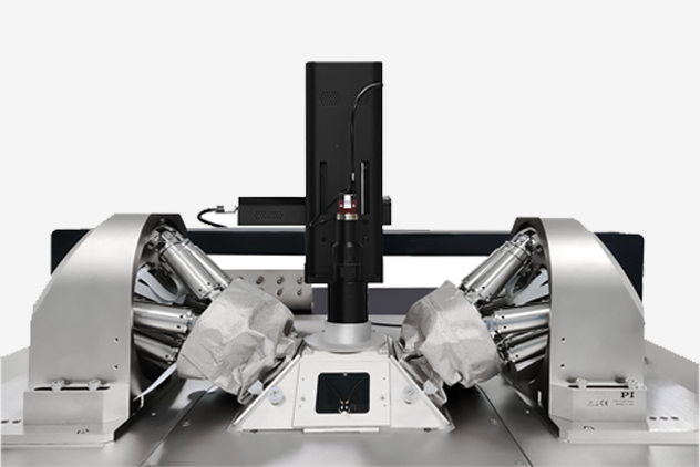
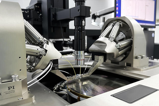
F1 High-Precision Double-Sided Fiber Alignment System *
No. Item A-005 Unit 1 Number of active axes 18 - Coarse positioning with spindle-driven axes 2 Active axes X, Y, Z, θX, θY, θZ - 3 Travel range in X, Y, Z ** ± 6.5, ± 16, ± 8.5 mm 4 Travel range in θX, θY, θZ ** ± 14.5, ± 10, ± 10 ° 5 Minimum incremental motion in X, Y, Z 0.1 μm 6 Max. velocity in X, Y, Z 10 mm/s 7 Sensor type Rotary encoder - 8 Drive type Brushless DC motor - Fine positioning with piezo-driven axes 9 Active axes X, Y, Z - 10 Travel range in X, Y, Z, closed loop 100 µm 11 Min. incremental motion, open-loop 0.3 nm 12 Min. incremental motion, closed-loop 2.5 nm 13 Linearity error, for the entire
travel range ***
2 % 14 Repeatability (bidirectional)
10% travel range
2 nm 15 Sensor type Incremental - 16 Drive type PICMA® - Alignment 17 Scanning time of spiraled area
scan 500 µm Ø ****
< 5 s 18 Scanning time of spiraled area
scan 100 µm Ø ****
< 1 s 19 Scanning time of spiraled area
scan 10 µm Ø ****
< 0.5 s 20 Signal optimization with gradient search, randomized with ±5 µm
(repeatability < 0.01 dB) *****
< 0.3 s Miscellaneous 21 Operating temperature range, mechanics 0 ~ 50 °C 22 Operating temperature range, controller 5 ~ 40 °C 23 Cable length 2 m Requirements for the optical power meter 24 Output signal Analog output - 25 Output voltage range, max. - 5 ~ 5 V 26 Bandwidth, min. 1 kHz 27 Noise level, max. -60 dBm * The related parameters, please refer to the manufacturer traceability index. This project is not verified on the client side
** The maximum travel ranges of the individual coordinates (X, Y, Z, θX, θY, θZ) are interdependent. The data for each axis shows its maximum travel range when all other axes are in the zero position of the nominal travel range and the default coordinate system is in use, or rather when the pivot point is set to 0,0,0. Changing the pivot point will reduce the travel range in θX, θY, θZ. Changing the orientation of the coordinate system, will change the travel range in X, Y, and Z
*** without polynomial linearization
**** typical time span for scanning the entire area and moving to the highest intensity ***** reaching the global maximum after first light has been found
Hexapod Motion Controller *
No. Item C-887.521 1 Input voltage range -5 ~ 5 V 2 Resolution ADC 16 bit 3 Bandwidth 5 kHz 4 Input impedance 15 kohm 5 Connector BNC 6 Processor Intel Atom dual core (1.8 GHz) 7 Reference switch input TTL 8 Communication interfaces TCP/IP 9 Command set futureC command set 10 User software futureC 11 Output voltage 24 V 12 Peak output current 6000 mA 13 Operating voltage 24 V(ext. power adapter included) 14 Maximum current consumption 8 A 15 Operating temperature range 5 ~ 40 °C 16 Mass 2.8 kg * The related parameters, please refer to the manufacturer traceability index. This project is not verified on the client side
Hexapod *
No. Item H-811K044 Unit Tolerance 1 Active axes X, Y, Z, θX, θY, θZ - - Motion and positioning 2 Travel range in X, Y, Z ** ± 17, ± 16, ± 6.5 mm - 3 Travel range in θX, θY, θZ ** ± 10, ± 10, ± 21 ° - 4 Single-actuator design resolution 10 nm - 5 Min. incremental motion X, Y 0.1 µm typ. 6 Min. incremental motion Z 0.05 µm typ. 7 Min. incremental motion θX, θY, θZ 1 µrad typ. 8 Backlash X, Y 0.2 µm typ. 9 Backlash Z 0.06 µm typ. 10 Backlash θX, θY 4 µrad typ. 11 Backlash θZ 4 µrad typ. 12 Repeatability X, Y ± 0.15 µm typ. 13 Repeatability Z ± 0.06 µm typ. 14 Repeatability θX, θY ± 2 µrad typ. 15 θZ 重复性 ± 3 µrad typ. 16 X, Y, Z 轴最大速度 10 mm/s - 17 θX, θY, θZ 最大速度 250 mrad/s - 18 X, Y, Z 轴典型速度 5 mm/s - 19 θX, θY, θZ 轴典型速度 120 mrad/s - Mechanical properties 20 Stiffness X, Y 0.7 N/µm - 21 Stiffness Z 8 N/µm - 22 Load (base plate horizontal /
any orientation)
5 / 2.5 kg max. 23 Holding force, de-energized (base plate horizontal / any orientation 15 / 2.5 N max. 24 Motor type Brushless DC motor - - Miscellaneous 25 Operating temperature range 0 ~ 50 °C - 26 Material Stainless steel, aluminum - - 27 Mass 2.2 kg ± 5% 28 Cable length 2 m ± 10 mm * The related parameters, please refer to the manufacturer traceability index. This project is not verified on the client side
** The maximum travel ranges of the individual coordinates (X, Y, Z, θX, θY, θZ) are interdependent. The data for each axis shows
its maximum travel range when all other axes are in the zero position of the nominal travel range and the default coordinate system is in use,
or rather when the pivot point is set to 0,0,0. Changing the pivot point will reduce the travel range in θX, θY, θZ. Changing the orientation of the
coordinate system, will change the travel range in X, Y, and Z
Modular Digital Piezo Controller *
No. Item E-712K255 1 Axes 6 2 Processor PC-based, 600 MHz, real-time operating system 3 Sampling rate, servo control 20 kHz 4 Sampling rate, sensor 20 kHz 5 Controller type P-I, two notch filters 6 Sensor type Capacitive 7 Sensor channels 6 8 Sensor bandwidth (-3 dB) 10 kHz 9 Sensor resolution 18 (interpolated: 20) bits 10 External synchronization Yes 11 Output voltage -30 ~ 135 V 12 Amplifier channels 8 13 Peak output power / channel* 25 W 14 Average output power / channel 8 W 15 Current limitation Short-circuit proof 16 Resolution DAC 20 bit 17 Temperature sensor Yes 18 Communication interfaces TCP/IP 19 Piezo / sensor connector Sub-D Mix 25W3 20 Digital inputs/outputs MDR20: 8 × TTL 21 Command set futureC command set 22 User software futureC 23 Application programming interfaces C / C++ / C# / VB.NET / MATLAB / Python, drivers for NI LabVIEW 24 Supported functions Wave generator, trigger I/O, macros 25 Linearization 4th-order polynomials, DDL option (Dynamic Digital Linearization) 26 Operating temperature range 5 ~ 40°C 27 Overheat protection Max. 75 °C, deactivation of the voltage output75 °C 28 Max. power consumption 225 W 29 Operating voltage 100 ~ 240 VAC, 50 ~ 60 Hz 30 Input voltage range ± 10 V 31 Resolution ADC 18 bit 32 Bandwidth 25 kHz 33 Input impedance 150 kohm 34 Connector LEMO EPG.00.302.NLN * The related parameters, please refer to the manufacturer traceability index. This project is not verified on the client side
Nanocube *
No. Item P-616K001 Unit Tolerance Motion and Positioning 1 Active axes X, Y, Z - - 2 Open-loop travel, -20 to 120 V 120 / axis µm + 20% / -0% 3 Closed-loop travel 100 / axis µm + 20% / -0% 4 Min. incremental motion,
closed-loop
2.5 nm typ. 5 Linearity error,
(for the entire travel range)
2% - typ. 6 Bidirectional repeatability 2 nm typ. Sensor 7 Sensor type Optical incremental sensors - - Mechanical properties 8 Stiffness 0.5 N/µm ± 10% 9 Unloaded resonant
frequency X, Y, Z
700 Hz ± 10% 10 Resonant frequency
with 30 g load X, Y, Z
380 Hz ± 20% 11 Push force capacity
(any orientation)
15 N max. 12 Holding force; passive
(any orientation)
15 N max. 13 Maximum permissible torque
for XYZ motion platform X, Y, Z
0.4 Nm max. Drive Properties 14 Drive type PICMA® P-885.50 - - 15 Electrical capacitance 1.5 / axis µF ± 20% 16 Dynamic operating
current coefficient
1.9 µA/(Hz x µm) ± 20% Miscellaneous 17 Operating temperature range -20 ~ 80 °C - 18 Material Aluminum, steel - - 19 Dimensions 40 × 40 × 40 mm - 20 Mass without cable 0.13 kg - 21 Mass with cable 0.32 kg - 22 Cable length 3 m ± 10 mm 23 Sensor / driver connection Sensor: HD D-Sub 26 (f)
Driver:: D-Sub 25W3 (m)
- - * The related parameters, please refer to the manufacturer traceability index. This project is not verified on the client side
F1 Dimensions and Weight
No. Item Semi-automated Fully-automated 1 Typical dimensions
(W x D x H)
~1500 x 1115 x 1543.5 mm *~2063 x 1620 x 1954 mm **2
Maximum dimensions
(W x D x H)
~1750 x 1465 x 1613.5 mm~2373 x 1620 x 2004 mm3 Main dimensions 
4 Main dimensions(Unit mm) 双边光纤对准系统
5 External view 6 Weight Probe station Thermal system
(Liquid Cooling)
Thermal system
(Air Cooling)
Loader ~ 850 kg~ 180 kg~ 180 kg~ 345 kg * These dimensions include the adjustable stands for LCD, mouse and keyboard. The dimensions are only typical values
** These dimensions include the adjustable stands for LCD, mouse and keyboard, and the tricolor light. The dimensions are only typical values
F1 Facility Planning
1 Environmental conditions Operating Ambient temperature: 17°C ~ 25°C, ± 0.2°C
Relative humidity: 20% ~ 60%
Storage Ambient temperature: 10°C ~ 30°C
Relative humidity: ≤ 50%
Storage time: ≤ 6 months
(When the storage time exceeds 6 months,it needs to be powered on for 24 hours)
Ambient vibration (including floor) On the horizontal floor, equivalent uniform live load ≥ 200 kg/㎡
Maximum level 100 micrometers/sec,rms (ISO Operating Theatre level) *
Laboratory cleanliness: General laboratory
(The requirements for the F1 operating and storage environment
described in this Manual must be met)
Recommended to be placed in Class-10,000 clean room and above **
2 Power Semi-automated probe station Probe station: single-phase 220 VAC ( +7%, -10%) ***,
50/60 Hz, 1800 VA, GB 10A socket
LCD, computer host, and vacuum pump: single-phase 220 VAC (+7%, -10%) ***,
50/60 Hz, 1000 VA, GB 10A socket (3-way, power strip)
Fully-automated probe station Probe station: single-phase 220 VAC (+7%, -10%) ***, 50/60 Hz, 1800 VA, GB 10A socket
LCD, computer host, and vacuum pump: single-phase 220 VAC (+7%, -10%) ***,
50/60 Hz, 1000 VA, GB 10A socket (3-way, power strip)
Loader: single-phase 220 VAC (+7%, -10%) ***, 50/60 Hz, 1000 VA, GB 10A socket
Thermal system Controller: single-phase 220 VAC (+7%, -10%) ***, 50/60 Hz, GB 10A socket
Chiller (Liquid cool): three-phase 380 VAC (+7%, -7%) ***, 50/60 Hz, GB 32A 5-core aviation socket
Chiller (Air cool): three-phase 380 VAC (+7%, -7%) ***, 50/60 Hz, GB 32A 5-core aviation socket
3 Clean Dry
Air ******
(CDA)
Room-temperature probe station Air pressure: 4.5 ~ 8 bar (65 ~ 116 psi)
Dew point: ≤ -20°C
Connector *****:
Semi-automated: 8 mm OD (CDA 1)
Fully-automated: 8 mm OD (CDA 1) and 8 mm OD (CDA 2)
High and low-temperature probe station Testing at low and high temperatures, the following conditions must be met to keep Chuck frost-free:
Air pressure: 4.5 ~ 8 bar (65 ~ 116 psi)
Continuous flow:
Liquid cool: ≥ 100 l/min @ 4.5 bar
Air cool: ≥ 400 l/min @ 4.5 bar
Dew point: ≤ -70°C (when the lowest test temperature is -60°C)
Oil less than 0.01 mg/m³ ****
Connector *****:
Semi-automated: 8 mm OD (CDA 1)
Fully-automated: 8 mm OD (CDA 1) and 8 mm OD (CDA 2)
4 Vacuum ****** Air pressure (absolute vacuum) ≤ 0.4 bar @ 10 l/min Air pressure (relative vacuum) ≤ - 0.6 bar @ 10 l/min Continuous flow ≥ 10 l/min Connector ***** Semi-automated: 8 mm OD (VAC 1)
Fully-automated: 8 mm OD (VAC 1) and 8 mm OD (VAC 2)
5 Accessories Air compressor Temperature range (liquid cool) Part Number Room temperature I-001 -60 ~ 150°C I-002 -60 ~ 200°C -60 ~ 300°C -40 ~ 150°C -40 ~ 200°C -40 ~ 300°C 0 ~ 100°C 0 ~ 200°C Room temperature ~ 150°C Room temperature ~ 200°C Room temperature ~ 300°C Vacuum pump - K-001 6
CDA and VAC Connectors * Refer to Generic vibration criteria for vibration-sensitive equipment
** Refer to the international standard ISO 14644-1
*** According to the requirements of the national standard GB/T 156-2007
**** According to the requirements of the international standard ISO8573-1
***** Refer to the international standard ISO 14743:2020
***** For the positions of interfaces CDA 1, CDA 2, VAC 1 and VAC 2, see the following CDA and VAC Connectors diagram
****** Measured in laboratory at Standard Ambient Temperature And Pressure (SATP). For more information on CDA pressure and flow,
please consult Eoulu
F1 Service Center *
Service category Service content Part Number Hardware service
(Installation)
• System installation (mass production mode) SRV-301 • System installation (analysis mode) SRV-501 • Accessory installation SRV-305 • System reinstallation SRV-306 • Instrument connection SRV-307 • Ground connection SRV-308 Hardware service
(Calibration)
• Accuracy calibration SRV-503 • Temperature calibration SRV-505 • Loader calibration SRV-506 Hardware service
(Training)
• Probe station operation
(mass production mode)
SRV-303 • Probe station operation (analysis mode) SRV-502 • RF calibration SRV-202 • Instrument operation SRV-203 Hardware service
(Others)
• Probe station PM PM-F1 • Probe station relocation RELO-F1 • Accompanying service SRV-201 Software service
(Installation)
• On-site installation SRV-101 • Remote installation SRV-103 Software service
(Update)
• Platform function SRV-607 • Platform version SRV-606 • Test script SRV-608 • Instrument driver SRV-609 • Plug-in update SRV-701 Software service
(Training)
• Software operation SRV-605 • Driver development SRV-603 • Script development SRV-702 Software service
(Others)
• Operation consultation SRV-706 • Troubleshooting SRV-703 • Accompanying service SRV-705 Application service • IV test SRV-707 • CV test SRV-708 • RF test SRV-709 • SiPh test SRV-801 • Blue tape test SRV-802 • Fixture test SRV-803 • MMIC test SRV-805 • Automatic test SRV-806 Delivery service • Urgent service SRV-807 • Insurance SRV-808 • Unloading SRV-809 • Exclusive vehicle SRV-901 • Storing SRV-902 • Upstairs delivery SRV-903 • Cleanup SRV-905 * For details of service quotation, please contact Eoulu's sales.
Product parameters are subject to change without prior notice.All product images are subject to the actual products, and Suzhou Eoulu System Integration Co., Ltd. reserves the interpretation right for the content.
Related Products
Please leave your contact information and our professionals will contact you as soon as possible!