The best probe station, made in China!

PRODUCTS

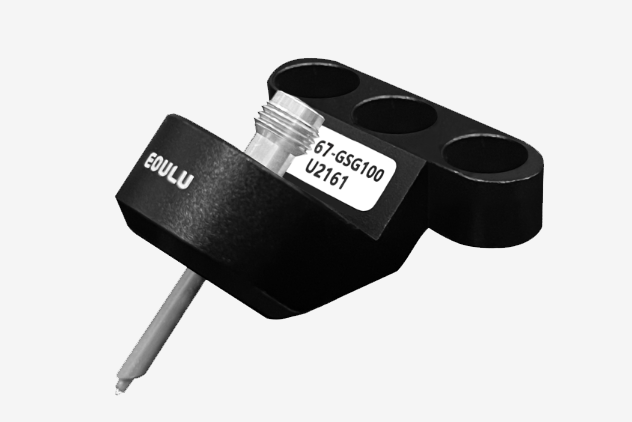
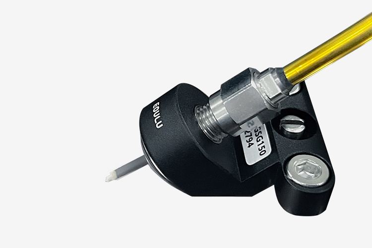
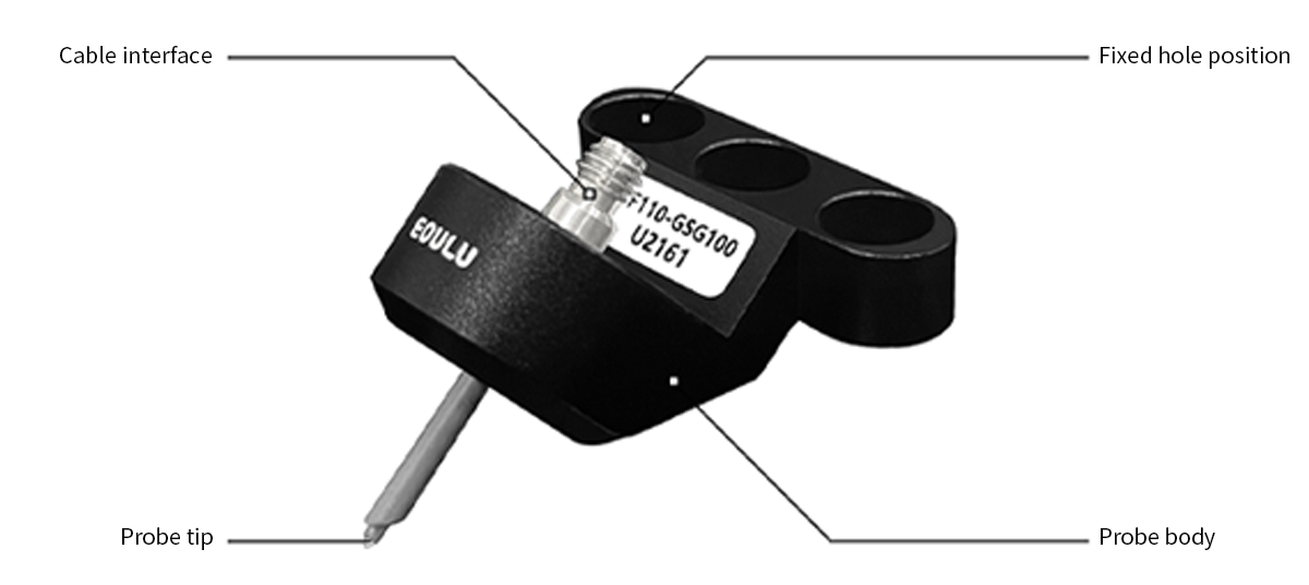
Single signal 67 GHz RF Probe
· Extremely low contact resistance and superior impedance control
· It can maintain signal integrity and stability during wide temperature range testing, and the data repeatability is extremely high
· Sky Series radio frequency probes are delivered quickly and repaired in China, with no need to wait
Category:
RF Probe
Contact Information
CONTACT NOW- Product Features
- Product Mix
- Product Parameters
- Instructions
-
Special tip design technology and ultra-long service life,suitable for mass production testing
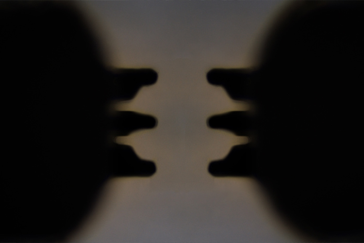
Pad unevenness compatibility up to 25 μm,suitable for testing uneven interfaces
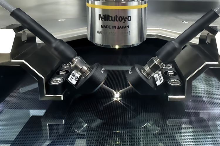
Very low contact resistance and insertion loss
Meet the wide temperature range test of -60℃~200℃
-
-
Selection Guide
Key Specifications Single-Signal Dual-Signal (Differential) LF Series RF Series HF Series LF Series RF Series HF Series Maximum Frequency 50 GHz 110 GHz 110 GHz 67 GHz 110 GHz 110 GHz Typical Insertion Loss @ 40 GHz **GSG,150 μm Pitch,Standard GSGSG,150 μm Pitch,Standard - 0.50 dB - 0.62 dB - 0.57 dB - 0.80 dB - 0.80 dB - 0.80 dB Typical Return Loss @ 40 GHz ** GSG,150 μm Pitch,Standard GSGSG,150 μm Pitch,Standard - 20.50 dB - 17.80 dB - 18.54 dB - 13.00 dB - 13.00 dB - 13.00 dB Typical Contact Resistance *** <10 mΩ <10 mΩ <10 mΩ <10 mΩ <10 mΩ <10 mΩ Tip Configuration GSG, GS,SG GSG, GS,SG GSG, GS,SG GSGSG, GSSG GSGSG, GSSG GSGSG, GSSG Probe Pitch ***** 50 μm ~ 1250 μm(25 μm step) 50 μm ~ 1250 μm(25 μm step) 50 μm ~ 1250 μm(25 μm step) 50 μm ~ 1250 μm(25 μm step) 50 μm ~ 1250 μm(25 μm step) 50 μm ~ 1250 μm(25 μm step) Typical Lifetime ****** >1,000,000 >1,000,000 >1,000,000 >1,000,000 >1,000,000 >1,000,000 Maximum Temperature 200°C 200°C 200°C 200°C 200°C 200°C Minimum Pad Size 70 × 70 μm 30 × 30 μm 30 × 30 μm 70 × 70 μm 30 × 30 μm 30 × 30 μm Features · Suitable for uneven wafer
· Stable testing
· High repeatability
· Long lifetime
· Fast delivery
· Ultra Low Contact Resistance
· Small contact marks
· Stable testing
· High repeatability
· Ultra low Contact Resistance
· Small contact marks
· Stable testing
· High repeatability
· Suitable for uneven wafer
· Stable testing
· High repeatability
· Long lifetime
· Fast delivery
· Ultra low Contact Resistance
· Small contact marks
· Stable testing
· High repeatability
· Ultra low Contact Resistance
· Small contact marks
· Stable testing
· High repeatability
Recommendation ******* · PCB Board Testing
· Mass Production Testing
· Filter Testing · Device Modeling Testing
· Characterization Testing
· PCB Board Testing
· Mass Production
· Filter Testing · Device Modeling Testing
· Characterization Testing
40 GHz Single-Signal : LF40 Series
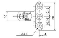
Electrical Specifications Dimensions — Typical ******** 1 Frequency Range DC ~ 40 GHz 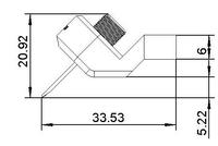 .
. 
2 Insertion Loss **
(GSG,150 μm Pitch,Standard)
Max Typical Min - 0.39 dB - 0.50 dB - 0.60 dB 3 Return Loss **
(GSG,150 μm Pitch,Standard)
Max Typical Min - 17.00 dB - 20.50 dB - 28.15 dB 4 Characteristic Impedance 50 Ω 5 Contact Resistance *** <10 mΩ 6 Maximum DC Current 3 A Dimensions — Mini ******** 7 Maximum DC Voltage 200 V 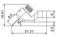
8 Maximum RF Power **** Standard High-power >4 W @ 40 GHz >7 W @ 40 GHz Mechanical Specifications 1 Tip Configuration GSG,GS,SG 2 Probe Pitch ***** 50 μm ~ 1250 μm(25 μm step) Dimensions — Slim ******** 3 Connector 2.92 mm(female) 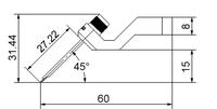
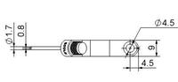
4 Probe Tip Material Nickel Alloy 5 Typical Lifetime ****** >1,000,000 6 Maximum Temperature 200°C 7
Minimum Pad Size 70 × 70 μm 8 Probe Shape Typical / Mini / Slim 9 Recommended Cable C40 Series Cables
40 GHz Single-Signal : RF40 Series
Electrical Specifications Dimensions — Typical ******** 1 Frequency Range DC ~ 40 GHz . 2 Insertion Loss **
(GSG,150 μm Pitch,Standard)
Max Typical Min - 0.43 dB - 0.62 dB - 0.69 dB 3 Return Loss **
(GSG,150 μm Pitch,Standard)
Max Typical Min - 15.25 dB - 17.80 dB - 19.33 dB 4 Characteristic Impedance 50 Ω 5 Contact Resistance *** <10 mΩ 6 Maximum DC Current 2 A Dimensions — Mini ******** 7 Maximum DC Voltage 200 V
8 Maximum RF Power **** Standard High-power >4 W @ 40 GHz >7 W @ 40 GHz Mechanical Specifications 1 Tip Configuration GSG,GS,SG 2 Probe Pitch ***** 50 μm ~ 1250 μm(25 μm step) Dimensions — Slim ******** 3 Connector 2.92 mm(female) 4 Probe Tip Material Copper Alloy 5 Typical Lifetime ****** >1,000,000 6 Maximum Temperature 200°C 7
Minimum Pad Size 30 × 30 μm 8 Probe Shape Typical / Mini / Slim 9 Recommended Cable C40 Series Cables 40 GHz Single-Signal : HF40 Series
Electrical Specifications Dimensions — Typical ******** 1 Frequency Range DC ~ 40 GHz . 2 Insertion Loss **
(GSG,150 μm Pitch,Standard)
Max Typical Min - 0.52 dB - 0.57 dB - 0.72 dB 3 Return Loss **
(GSG,150 μm Pitch,Standard)
Max Typical Min - 16.13 dB - 18.54 dB - 20.45 dB 4 Characteristic Impedance 50 Ω 5 Contact Resistance *** <10 mΩ 6 Maximum DC Current 2 A 7 Maximum DC Voltage 200 V 8 Maximum RF Power **** Standard High-power >4 W @ 40 GHz >7 W @ 40 GHz Mechanical Specifications 1 Tip Configuration GSG,GS,SG 2 Probe Pitch ***** 50 μm ~ 1250 μm(25 μm step) 3 Connector 2.92 mm(female) 4 Probe Tip Material Copper Alloy 5 Typical Lifetime ****** >1,000,000 6 Maximum Temperature 200°C 7
Minimum Pad Size 30 × 30 μm 8 Probe Shape Typical / Mini / Slim 9 Recommended Cable C40 Series Cables 50 GHz Single-Signal : LF50 Series
Electrical Specifications Dimensions — Typical ******** 1 Frequency Range DC ~ 50 GHz 2 Insertion Loss **
(GSG,150 μm Pitch,Standard)
Max Typical Min - 0.48 dB - 0.70 dB - 0.90 dB 3 Return Loss **
(GSG,150 μm Pitch,Standard)
Max Typical Min - 10.70 dB - 15.00 dB - 20.60 dB 4 Characteristic Impedance 50 Ω 5 Contact Resistance *** <10 mΩ 6 Maximum DC Current 3 A Dimensions — Mini ******** 7 Maximum DC Voltage 200 V 8 Maximum RF Power **** Standard High-power >3.5 W @ 50 GHz >6.5 W @ 50 GHz Mechanical Specifications 1 Tip Configuration GSG,GS,SG 2 Probe Pitch ***** 50 μm ~ 1250 μm(25 μm step) Dimensions — Slim ******** 3 Connector 1.85 mm(female) 4 Probe Tip Material Nickel Alloy 5 Typical Lifetime ****** >1,000,000 6 Maximum Temperature 200°C 7 Minimum Pad Size 70 × 70 μm 8 Probe Shape Typical / Mini / Slim 9 Recommended Cable C50 Series Cables 50 GHz Single-Signal : RF50 Series
Electrical Specifications Dimensions — Typical ******** 1 Frequency Range DC ~ 50 GHz 2 Insertion Loss **
(GSG,150 μm Pitch,Standard)
Max Typical Min - 0.53 dB - 0.59 dB - 0.63 dB 3 Return Loss **
(GSG,150 μm Pitch,Standard)
Max Typical Min - 14.67 dB - 17.17 dB - 20.42 dB 4 Characteristic Impedance 50 Ω 5 Contact Resistance *** <10 mΩ 6 Maximum DC Current 2 A Dimensions — Mini ******** 7 Maximum DC Voltage 200 V 8 Maximum RF Power **** Standard High-power >3.5 W @ 50 GHz >6.5 W @ 50 GHz Mechanical Specifications 1 Tip Configuration GSG,GS,SG 2 Probe Pitch ***** 50 μm ~ 1250 μm(25 μm step) Dimensions — Slim ******** 3 Connector 1.85 mm(female) 4 Probe Tip Material Copper Alloy 5 Typical Lifetime ****** >1,000,000 6 Maximum Temperature 200°C 7 Minimum Pad Size 30 × 30 μm 8 Probe Shape Typical / Mini / Slim 9 Recommended Cable C50 Series Cables 50 GHz Single-Signal : HF50 Series
Electrical Specifications Dimensions — Typical ******** 1 Frequency Range DC ~ 50 GHz 2 Insertion Loss **
(GSG,150 μm Pitch,Standard)
Max Typical Min - 0.53 dB - 0.59 dB - 0.63 dB 3 Return Loss **
(GSG,150 μm Pitch,Standard)
Max Typical Min - 14.67 dB - 17.17 dB - 20.42 dB 4 Characteristic Impedance 50 Ω 5 Contact Resistance *** <10 mΩ 6 Maximum DC Current 2 A 7 Maximum DC Voltage 200 V 8 Maximum RF Power **** Standard High-power >3.5 W @ 50 GHz >6.5 W @ 50 GHz Mechanical Specifications 1 Tip Configuration GSG,GS,SG 2 Probe Pitch ***** 50 μm ~ 1250 μm(25 μm step) 3 Connector 1.85 mm(female) 4 Probe Tip Material Copper Alloy 5 Typical Lifetime ****** >1,000,000 6 Maximum Temperature 200°C 7 Minimum Pad Size 30 × 30 μm 8 Probe Shape Typical 9 Recommended Cable C50 Series Cables 67 GHz Single-Signal : RF67 Series
Electrical Specifications Dimensions — Typical ******** 1 Frequency Range DC ~ 67 GHz .
2 Insertion Loss **
(GSG,150 μm Pitch,Standard)
Max Typical Min - 0.65 dB - 0.87 dB - 1.09 dB 3 Return Loss **
(GSG,150 μm Pitch,Standard)
Max Typical Min - 12.55 dB - 15.68 dB - 18.65 dB 4 Characteristic Impedance 50 Ω 5 Contact Resistance **** <10 mΩ 6 Maximum DC Current 2 A Dimensions — Mini ******** 7 Maximum DC Voltage 200 V 8 Maximum RF Power **** Standard High-power >3 W @ 67 GHz >6 W @ 67 GHz Mechanical Specifications 1 Tip Configuration GSG,GS,SG 2 Probe Pitch ***** 50 μm ~ 1250 μm(25 μm step) Dimensions — Slim ********
3 Connector 1.85 mm(female) 4 Probe Tip Material Copper Alloy 5 Typical Lifetime ****** >1,000,000 6 Maximum Temperature 200°C 7 Minimum Pad Size 30 × 30 μm 8 Probe Shape Typical / Mini / Slim 9 Recommended Cable C67 Series Cables 67 GHz Single-Signal : HF67 Series
Electrical Specifications Dimensions — Typical ******** 1 Frequency Range DC ~ 67 GHz . 2 Insertion Loss **
(GSG,150 μm Pitch,Standard)
Max Typical Min - 0.65 dB - 0.73 dB - 0.79 dB 3 Return Loss **
(GSG,150 μm Pitch,Standard)
Max Typical Min - 15.22 dB - 15.50 dB - 15.77 dB 4 Characteristic Impedance 50 Ω 5 Contact Resistance *** <10 mΩ 6 Maximum DC Current 2 A 7 Maximum DC Voltage 200 V 8 Maximum RF Power **** Standard High-power >3 W @ 67 GHz >6 W @ 67 GHz Mechanical Specifications 1 Tip Configuration GSG,GS,SG 2 Probe Pitch ***** 50 μm ~ 1250 μm(25 μm step) 3 Connector 1.85 mm(female) 4 Probe Tip Material Copper Alloy 5 Typical Lifetime ****** >1,000,000 6 Maximum Temperature 200°C 7 Minimum Pad Size 30 × 30 μm 8 Probe Shape Typical 9 Recommended Cable C67 Series Cables 110 GHz Single-Signal : RF110 Series
Electrical Specifications Dimensions — Typical ******** 1 Frequency Range DC ~ 110 GHz .2 Insertion Loss **
(GSG,150 μm Pitch,Standard)
Max Typical Min - 0.96 dB - 1.13 dB - 1.37 dB 3 Return Loss **
(GSG,150 μm Pitch,Standard)
Max Typical Min - 11.60 dB - 16.86 dB - 19.24 dB 4 Characteristic Impedance 50 Ω 5 Contact Resistance *** <10 mΩ 6 Maximum DC Current 2 A Dimensions — Mini ******** 7 Maximum DC Voltage 200 V Mechanical Specifications 1 Tip Configuration GSG 2 Probe Pitch ***** 50 μm ~ 150 μm(25 μm step) 3 Connector 1.0 mm(female) Dimensions — Slim ********
4 Probe Tip Material Copper Alloy 5 Typical Lifetime ****** >1,000,000 6 Maximum Temperature 200°C 7 Minimum Pad Size 30 × 30 μm 8 Probe Shape Typical / Mini / Slim 9 Recommended Cable C110 Series Cables 110 GHz Single-Signal : HF110 Series
Electrical Specifications Dimensions — Typical ******** 1 Frequency Range DC ~ 110 GHz .2 Insertion Loss **
(GSG,150 μm Pitch,Standard)
Max Typical Min - 0.96 dB - 1.13 dB - 1.37 dB 3 Return Loss **
(GSG,150 μm Pitch,Standard)
Max Typical Min - 11.60 dB - 16.86 dB - 19.24 dB 4 Characteristic Impedance 50 Ω 5 Contact Resistance *** <10 mΩ 6 Maximum DC Current 2 A 7 Maximum DC Voltage 200 V Mechanical Specifications 1 Tip Configuration GSG 2 Probe Pitch ***** 50 μm ~ 150 μm(25 μm step) 3 Connector 1.0 mm(female) 4 Probe Tip Material Copper Alloy 5 Typical Lifetime ****** >1,000,000 6 Maximum Temperature 200°C 7 Minimum Pad Size 30 × 30 μm 8 Probe Shape Typical 9 Recommended Cable C110 Series Cables
** The test data and specifications depend on individual process conditions, the data may be different for different probe parameters.Not all specifications are valid at the same time
** The recommended standard probe pitch is 75 μm ~ 250 μm
** When purchasing and using our RF probe and Calibration Substrate for the first time, it is recommended to purchase
on-site installation and calibration training services
** For any problems about hardware construction, cable connection, instrument setting, equipment operations, system calibration, test
process and data analysis during the test, visit "Service" at the Eoulu official website,
and purchase on-site accompaniment services for hardware and
software testing, or purchase the Eoulu future series software to simplify test operations and obtain test results easily and quickly
*** Rc on Au
**** Power test environment (Watts CW @ 20°C)
**** The high-power RF probes are customized products, please contact Eoulu for details
***** The typical probe pitch 50 μm ~ 1250 μm only applies to 40 GHz / 50 GHz / 67 GHz probes, and the typical probe pitch of 110 GHz and
above is 50 μm ~ 150 μm
***** 3000 μm (wide pitch) RF probes need to be customized
****** Typical lifetime on Al pads, room temperature
****** The typical lifetime test of RF probe has been verified in the Eoulu laboratory. For details, please refer to the RF probe lifetime verification
video in Eoulu’s official website and the Eoulu RF Probe Lifetime Verification Report
******* The test applications listed in the table are recommended by our company. Applications not listed may still be compatible.
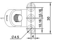
******** Probe dimensions are in mm
Product parameters are subject to change without prior notice.All product images are subject to the actual products, and Suzhou Eoulu System Integration Co., Ltd. reserves the interpretation right for the content.
Related Products
Please leave your contact information and our professionals will contact you as soon as possible!